Create Pulse Width Modulation from VHDL
This topic is an example of how to create pulse width modulation work with the Zynq processing system.
Example PWM_VHDL.VHD VHDL code
library ieee;
use ieee.std_logic_1164.all;
use ieee.std_logic_arith.all;
use ieee.std_logic_unsigned.all;
entity pwm is
generic(
g_width : integer range 1 to 99 := 12; -- the number of bits used to represent amplitude value
g_div_factor_freq : integer := 2
);
port(
i_clk : in std_logic; -- input clock signal
i_reset : in std_logic;
i_sine_ampl : in std_logic_vector(g_width-1 downto 0); -- current amplitude value of the sine signal
o_ena_freq_trig : out std_logic ; --
o_pwm_out : out std_logic ; -- pulse width modulated signal
o_pwm_out2 : out std_logic
);
end;
architecture rtl of pwm is
type state_type is (load_new_ampl, pwm_high, pwm_low); -- states s0, s1, s2
signal state: state_type := load_new_ampl ;
signal ena_freq_trig : std_logic := '0'; -- clock enable signal for the fsm
signal threshold : integer range 0 to ((2**g_width)-1) := 0; -- integer range 0 to 4095 (in our case)
signal count : integer range 0 to ((2**g_width)-1) := 0; -- integer range 0 to 4095 (in our case)
signal r_pwm_out : std_logic;
attribute mark_debug: string ;
attribute mark_debug of ena_freq_trig : signal is "True";
attribute mark_debug of threshold : signal is "True";
attribute mark_debug of count : signal is "True";
attribute mark_debug of r_pwm_out : signal is "True";
begin
process1: process (i_clk,i_reset)
begin
if i_reset= '0' then
r_pwm_out <= '0';
elsif rising_edge(i_clk) then
if (ena_freq_trig = '1') then
case state is
when load_new_ampl =>
threshold <= conv_integer (i_sine_ampl);
count <= 0;
if (i_sine_ampl > 0) then
state <= pwm_high;
r_pwm_out <='1';
elsif (i_sine_ampl = 0) then
state <= pwm_low;
r_pwm_out <='0';
end if;
when pwm_high =>
count <= count + 1;
if (count < ((2**g_width)-1) and count < i_sine_ampl) then
state <= pwm_high;
r_pwm_out <='1';
elsif (count = ((2**g_width)-1)) then
state <= load_new_ampl;
elsif (count < ((2**g_width)-1) and count = i_sine_ampl) then
state <= pwm_low;
r_pwm_out <='0';
end if;
when pwm_low =>
count <= count + 1;
if (count < ((2**g_width)-1)) then
state <= pwm_low;
r_pwm_out <='0';
elsif (count = ((2**g_width)-1)) then
state <= load_new_ampl;
end if;
end case;
end if;
end if;
end process process1;
o_ena_freq_trig <=ena_freq_trig ;
o_pwm_out <=r_pwm_out ;
o_pwm_out2 <=r_pwm_out ;
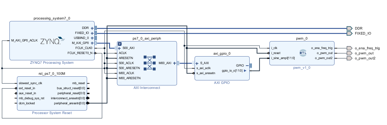
fsm_ce: entity work.frequency_trigger(rtl) -- instance of the frequency trigger
generic map (
g_div_factor_freq => g_div_factor_freq
)
port map (
i_clk => i_clk,
i_reset => i_reset,
o_freq_trig => ena_freq_trig
);
end;
Write test bench then simulation and check result
library ieee;
    use ieee.std_logic_1164.all;
    use ieee.std_logic_arith.all;
    use ieee.std_logic_unsigned.all;
entity pwm_tb is
    generic(
        width_g                : integer range 1 to 99 := 12         -- the number of bits used to represent amplitude value
        );
end;
architecture Behavioral_tb of pwm_tb is
    signal i_clk_tb        : std_logic := '0';     -- input clock signal
    signal i_reset_tb     : std_logic := '1';
    signal i_sine_out_tb   : std_logic_vector(width_g-1 downto 0) := "001101011100";         -- current amplitude value of the sine signal
    signal o_pwm_out_tb        : std_logic ;                  -- pwm signal


begin

    dut1 : entity work.pwm                               -- pwm instance
        generic map(
            g_width                       =>  width_g,
            g_div_factor_freq             => 2
            )
        port map(
            i_clk        => i_clk_tb,
            i_reset      => i_reset_tb,
            i_sine_ampl     => i_sine_out_tb,
            o_pwm_out       => o_pwm_out_tb
            );

    i_clk_tb <=  not (i_clk_tb) after 5ns;


end Behavioral_tb;
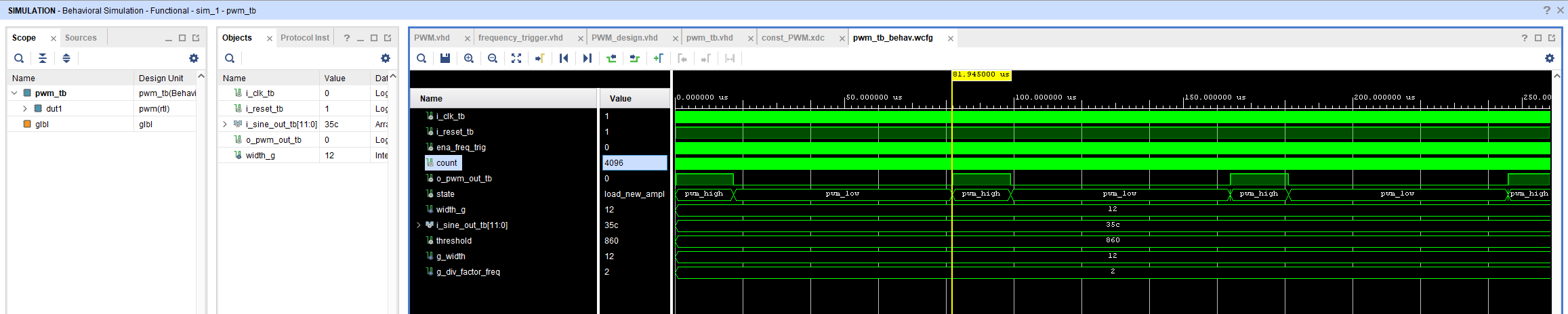
Here is the simulation result
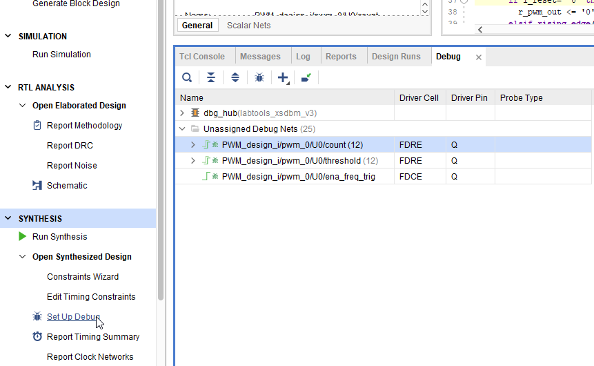
Debug by using ILA( Integrated Logic Analyzer (ILA)
The ILA can be used to monitor the internal signal in design. We can verify results from the signal waveform which is created by Vivado tools.
The method of how to set up ILA in RTL code is shown in the step below.
1. After completing the simulation of the PWM_VHDL.VHD file, we have to add the attribute mark (mark_debug) for creating debug circuit as shown in the below picture.
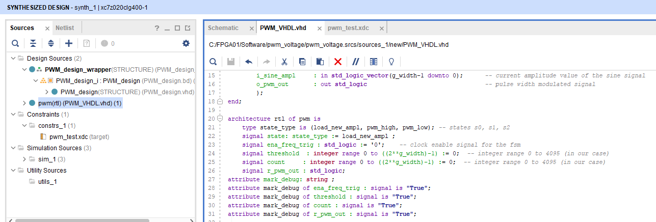
2. Click Set up Debug signal in the synthesis then select the signals that we want to debug.